
Diva Pico - Project Diva Style Mini Controller

Features:
- It's small, but the buttons are still decent.
- Works as a Nintendo Switch controller.
- 16 slider keys.
- Command line of rich features.
- All source files open.
Thanks to many respectful guys/companies who made their tools or materials free or open source (KiCad, OnShape, InkScape, Raspberry things).
Special thanks to community developers that inspired me and helped me: CrazyRedMachine (https://github.com/CrazyRedMachine).
Notes
This one is relatively easy to build compared with my other projects like IIDX Pico or Teeny. You can check out my other cool projects.
-
Popn Pico: https://github.com/whowechina/popn_pico
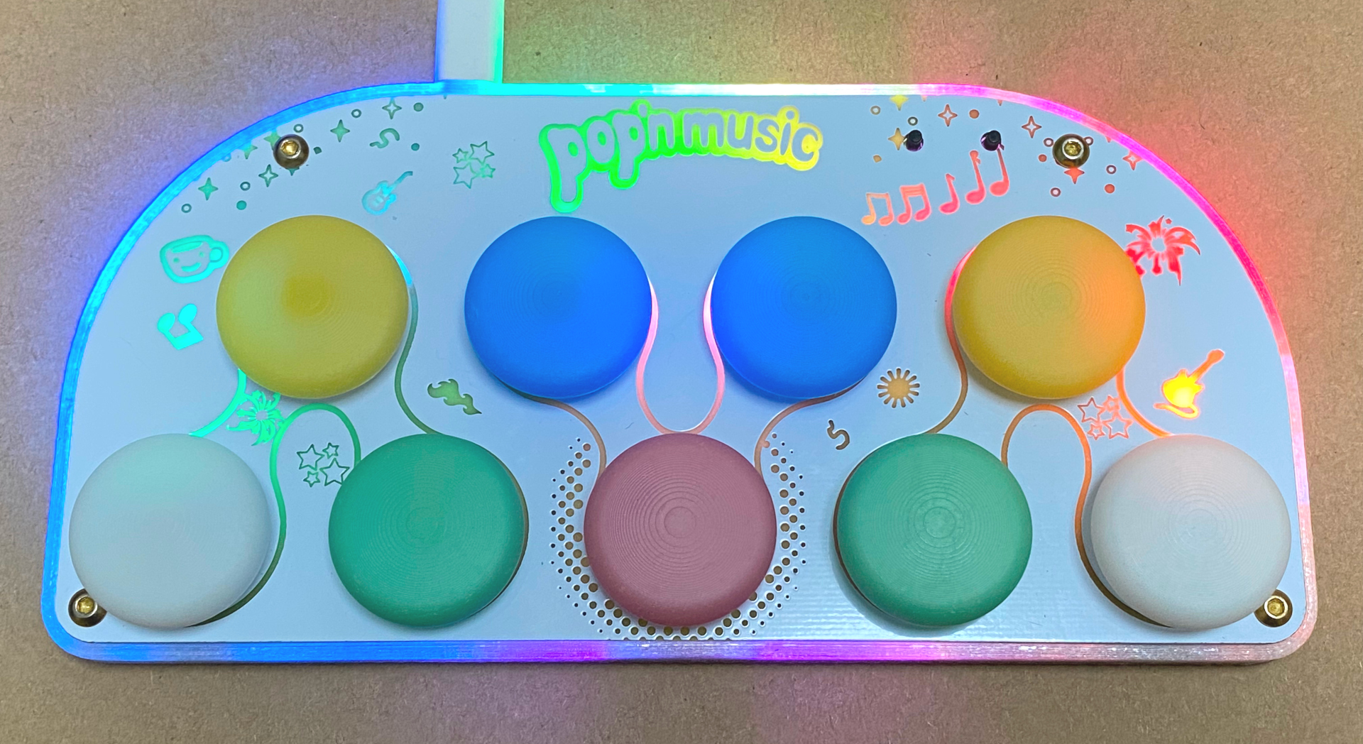
-
IIDX Pico: https://github.com/whowechina/iidx_pico
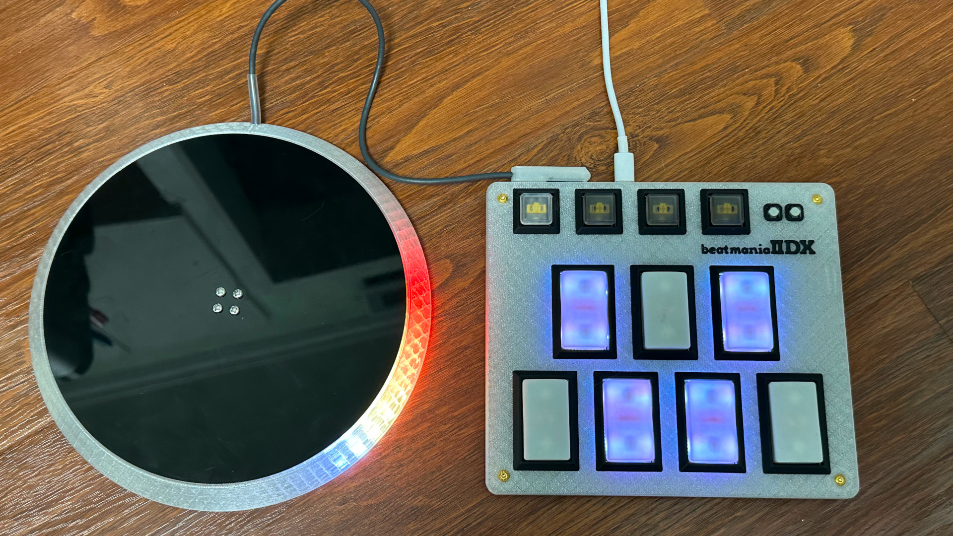
-
IIDX Teeny: https://github.com/whowechina/iidx_teeny
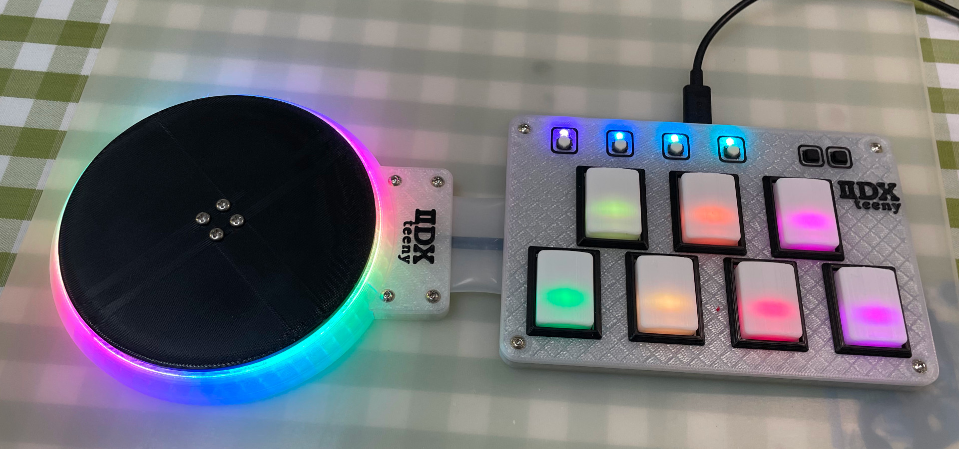
-
Mai Pico: https://github.com/whowechina/mai_pico
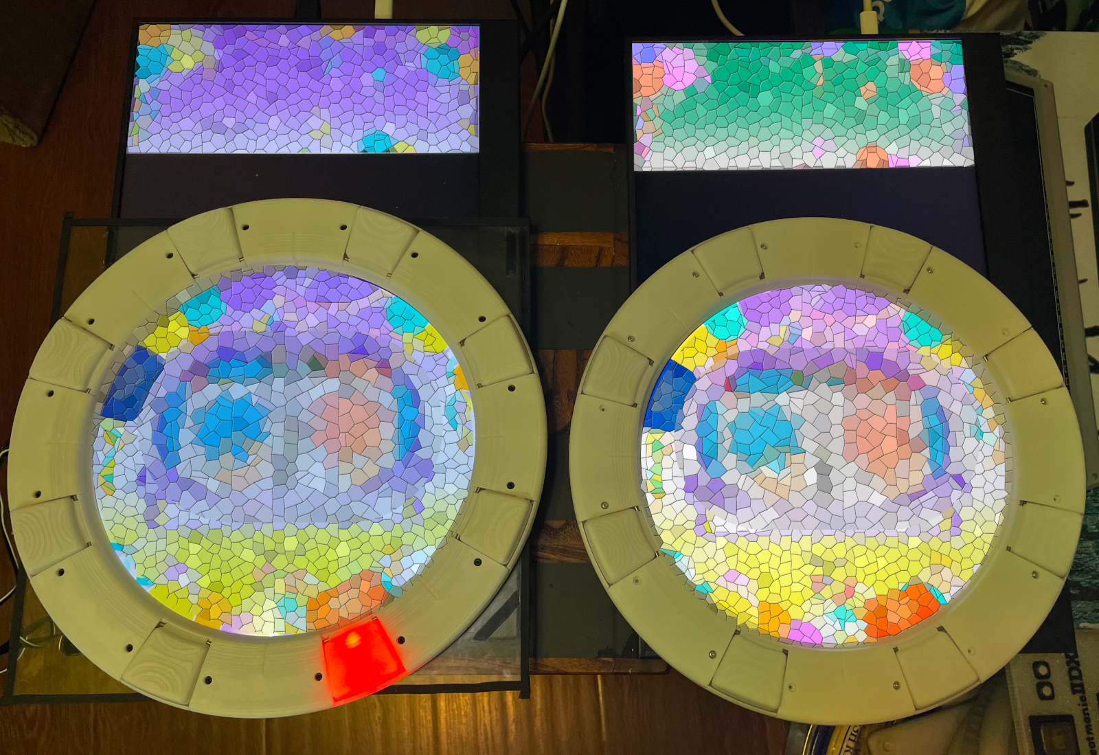
-
Chu Pico: https://github.com/whowechina/chu_pico
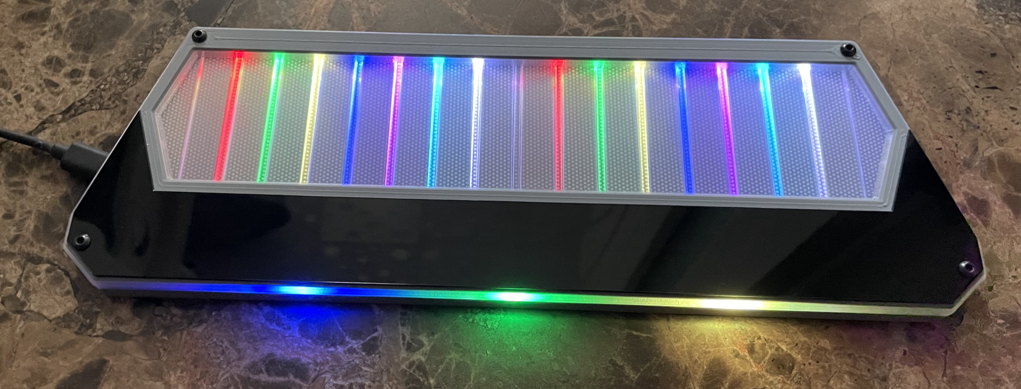
This Diva Pico project:
- Heavily depends on 3D printing, you need a Bambu 3D printer (X1, P1 or A1, not the mini version).
- Requires skills to solder tiny components.
Disclaimer
I made this project in my personal time with no financial benefit or sponsorship. I will continue to improve the project. I have done my best to ensure that everything is accurate and functional, there's always a chance that mistakes may occur. I cannot be held responsible for any loss of your time or money that may result from using this open source project. Thank you for your understanding.
About the License
It's CC-NC. So DIY for yourself and for your friend, don't make money from it.
HOW TO BUILD
Frequently Made Mistakes
Many DIY enthusiasts commonly make certain mistakes during the building process. Please proceed with extra caution to avoid these.
- MISTAKE: Soldering everything together without conducting intermediate testing.
Remember, even professional engineers can make mistakes. It becomes significantly harder to identify the root cause of a problem when all components are already assembled or soldered. Therefore, it's advisable to solder and test in stages. The firmware is designed to function correctly even with some components missing, which is good for testing. - MISTAKE: Neglecting to cut the ADDR pin trace on the MPR121 module.
The MPR121 module in the market has the ADDR pin pre-connected to ground. But the board expects a floating ADDR pin, otherwise the ADDR pin will short the circuit. Please verify your "CUT" using a multimeter. - MISTAKE: Rushing to replace components when something fails.
Be aware that desoldering and soldering large SMD components is a challenging task. It carries the risk of damaging the component or the PCB board. Patience and caution are crucial. Look at the schematics and PCB design files and ask help from community first. - MISTAKE: Prematurely assuming that the Raspberry Pi Pico or other modules are faulty.
While it's possible that these components could be defective, more often than not, the issue lies in the soldering. Therefore, questioning the integrity of these components should be your last resort.
PCB
-
Go JLCPCB and make order with the gerber zip file (latest
Production\PCB\diva_main_xxx.zip), regular FR-4 board, black color, thickness is 1.6mm.

-
1x Rasberry Pico Pi Pico or pin-to-pin compatible clones.
https://www.raspberrypi.com/products/raspberry-pi-pico
Sticking a thin scotch tape to avoid short-circuit is a good idea.

-
16x WS2812B-4020 side-facing RGB LEDs for the slider.
https://www.lcsc.com/product-detail/Light-Emitting-Diodes-LED_Worldsemi-WS2812B-4020_C965557.html -
9x WS2812B-3528 RGB LEDs for the buttons.
-
1x 0603 10ohm resistor (R3), or if you feel it's not challenging, go with SN74LV1T34DBVR (SOT-23-5) level shifter (U8), you only need either of them. https://www.lcsc.com/product-detail/Buffer-Driver-Transceiver_Texas-Instruments-SN74LV1T34DBVR_C100024.html
-
2x MPR121 modules, there're many types in the market, choose ones like this.
https://www.sparkfun.com/products/retired/9695
Before solder MP121 module to the main PCB board, remember to cut (unshort) the ADDR pin which is short by default.

There's not enough space for the whole height of MPR121 module plus the lead pads. So you need to solder the module like the picture shows below. -
8x 0603 1uF (0.1~1uF all fine) capacitors (C1 to C8), OPTIONAL, recommended.
-
4x Kailh choc v1 switches, use heavy linear ones (dark yellow is the best, the force is around 70gf).

-
2x Alps SKSTAAE010 tactile switches. https://tech.alpsalpine.com/e/products/detail/SKSTAAE010/
-
1x Omron B3F-4005 or B3F-4000 micro-switch. https://www.mouser.com/ProductDetail/Omron-Electronics/B3F-4000?qs=B3tblJ0Nlt8c5sbFRctxww%3D%3D
-
3M 5421 UHMW PE film tape, important for button feel. https://www.3m.com/3M/en_US/p/d/b40069119/ You need to apply tapes to the contact surface of button to switch and button to base clamp.


Light Guide Panel
- Find a service to cut a light guide panel or a frosted acrylic panel. It's a perfect rectangle, the size is 240mm*42mm, 1.8mm to 2.0mm thickness, so you don't need a CAD file.


3D Printing
-
You might need a Bambu 3D printer:
-
Parts are designed to perfectly fit in its 256mm*256mm print bed.
-
Its AMS system works great for multi-color printing.
-
PLA, PETG, ABS are all OK.
-
The color "Arctic Whisper" works best for the main body.
-
Layer height: 0.2mm
-
Support: Yes, always.
-
-
Base:
Production\3D\diva_pico_base.stl. -
Cover Base:
Production\3D\diva_pico_cover_base.stl. -
Cover:
Production\3D\diva_pico_cover.3mf, with optional multi-color support. -
Buttons:
Production\3D\diva_pico_buttons_*_*.3mf, with multi-color support. Note that components (the hinge, the seat and the logos on it) are mixed in one file, you need to cherry-pick before printing.
You have two options for the hinge, one is fixed hinge, the other is rotating hinge. For rotating when, you need a steel 2mm*50mm shaft. Rotating one feels better, but slightly difficult to assemble.


From top to bottom:
- Cover
- Cover Base + Light Guide Panel
- Buttons
- PCB
- Base
You need 6x M3*10mm regular screws to fix all things.
6x silicone anti-slip pads can be applied to the bottom side of the base to provide stability when playing.
Button dome choices
- Go find a servie, they blow acrylic to domes according to your numbers. The numbers are: 42mm outer diameter, 18mm outer height, made from 2mm clear acrylic, no brim. I find this most perfect. And you need to print 42mm buttons.

- Go buy 60mm dome buttons with 48mm diameter dome. I found there're two types, one is perfect and inner diameter is 46mm (the left side one), the other is too tall and inner diameter is 45mm (the right side one). You need to print the buttons according to what dome you get.


Firmware
- UF2 file is in
Production\Firmwarefolder. - For the new build, hold the BOOTSEL button while connect the USB to a PC, there will be a disk named "RPI-RP2" showed up. Drag the UF2 firmware binary file into it. That's it. There's a small hole at the bottom side of the Diva Pico, it is facing right to the BOOTSEL button.
- It has a command line to do configuration. You can use this Web Serial Terminal to connect to the USB serial port of the Diva Pico. (Note: "?" is for help)
https://googlechromelabs.github.io/serial-terminal/
CAD Source File
I'm using OnShape free subscription. It's powerful but it can't archive original designs to local, so I can only share the link here. STL/DXF/DWG files are exported from this online document.
https://cad.onshape.com/documents/d9e9c1de2d4b98d5eaf21d07/w/7c216f367b558e083eb1f468/e/4536bf9859137db81313ff87?configuration=List_ilV09d08Sdz7FZ%3DButton_48&renderMode=0&uiState=65923e1383b3106c15b5c996